For a flow along a channel without heated, after it is fully developed, the velocity pattern at a cross area is parabolic. However, if the flow is also heated, the parabolic velocity pattern will be twisted because of the viscosity dependency of the fluid (this is true for many types of liquid). This phenomenon is pictorially shown as the figure below, in which (a) is the parabolic velocity profile, and (b) is the distorted profile in a heated duct due to the temperature dependency of the fluid viscosity.

Denote the duct height as H, duct length as L, fluid density as
in which
Anyway, I select this example to show a simple CFD calculation, because its simple geometry. Using SALOME we can very quickly build up a geometry and then mesh it. Probably an expected structured mesh of the channel can be like this. It is better to have dense mesh near the inlet and the walls of the duct.

Geometry and mesh using SALOME
According to the philosophy of executing commands on terminals, I'll use python scripts to re-perform the procedure of modelling in SALOME.
#######################################################################

# Geometry construction and meshing creation for a typical

#   2d channel flow between two infinite parallel plates.

#

# Written by: salad

#   Manchester, UK

#   06/02/2010

#######################################################################
How to execute these scripts? New a blank study in SALOME and then a 'Python Console' can be seen at the bottom of the window. Input or copy scripts into the console and press Enter to execute them. Scripts can also be saved in a .py file, and with the menu item 'File >> Load Script...' a dialog 'Load python script' can help load script files and execute them as a batch. 'Ctrl+T' is the shortcut to call the dialog.
Ok, let's start. 1. Import the necessary libraries and define the related dimensions. We are going to build a duct with height 5 mm and length 100 mm.
import os

import sys

import salome

from math import *

from geompy import *

import copy


# basic unit

unit = 0.001

# extrusion length

extru = unit


duct_height = unit * 5

duct_length = unit * 100
'extru' is the extrusion length along the z axis. This length will be meshed with only one cell. Actually Code_Saturne only handles 3D meshes with FVM. Therefore, to simulate a 2D mesh, it is a good practice to extrude the 2D mesh with a 1 cell layer thickness.
2. Build the basic coordinate.
#

# basic coordinate

#

p0 = MakeVertex(0, 0, 0)

dx = MakeVectorDXDYDZ(unit, 0, 0)

dy = MakeVectorDXDYDZ(0, unit, 0)

dz = MakeVectorDXDYDZ(0, 0, unit)

addToStudy(p0, "p0")

addToStudy(dx, "dx")

addToStudy(dy, "dy")

addToStudy(dz, "dz")


print "basic coordinate built..."
3. Construct the channel geometry. The geometry modelling procedure can be briefly expressed as: points => edges => faces => extrusion. Points are constructed with coordinates, edges are defined by linking points, and faces are then defined by specifying its edges. Finally extrusion helps convert the 2D geometry to 3D.
#

# geometry construction

#


# points

p1 = MakeVertex(duct_length, 0, 0)

p2 = MakeVertex(0, duct_height, 0)

p3 = MakeVertex(duct_length, duct_height, 0)


# build edges

e0 = MakeEdge(p0, p1)

e1 = MakeEdge(p2, p3)

e2 = MakeEdge(p0, p2)

e3 = MakeEdge(p1, p3)


# build face

f_duct = MakeFaceWires([e0, e1, e2, e3], 1)


# extrude along the z axis

v_duct = MakePrismVecH(f_duct, dz, extru)

addToStudy(v_duct, "v_duct")


print "channel geometry constructed..."
4. Define the groups. Groups are necessary because they correspond to the boundaries used during CFD calculations. Here we define the geometry groups and these groups will then be encapsulated into mesh groups later. Mesh groups will be used to define boundary conditions when using Code_Saturne.
Firstly, define the face groups. Functions used in the python script can be looked up in the SALOME document.
# FACE groups definition:

# 1. inlet

# 2. outlet

# 3. bottom

# 4. top

# 5. sym


# sym is declared and filled

sub_faces = SubShapeAllSorted(v_duct, ShapeType["FACE"])

g_sym = CreateGroup(v_duct, ShapeType["FACE"])

UnionList(g_sym, sub_faces)


# inlet

sub_faces = GetShapesOnPlane(v_duct, ShapeType["FACE"], dx, GEOM.ST_ON)


g_inlet = CreateGroup(v_duct, ShapeType["FACE"])

UnionList(g_inlet, sub_faces)

DifferenceList(g_sym, sub_faces)


addToStudyInFather(v_duct, g_inlet, "inlet")


# outlet

sub_faces = GetShapesOnPlaneWithLocation(v_duct, ShapeType["FACE"], dx, p1, GEOM.ST_ON)


g_outlet = CreateGroup(v_duct, ShapeType["FACE"])

UnionList(g_outlet, sub_faces)

DifferenceList(g_sym, sub_faces)


addToStudyInFather(v_duct, g_outlet, "outlet")


# bottom

sub_faces = GetShapesOnPlane(v_duct, ShapeType["FACE"], dy, GEOM.ST_ON)


g_bottom = CreateGroup(v_duct, ShapeType["FACE"])

UnionList(g_bottom, sub_faces)

DifferenceList(g_sym, sub_faces)


addToStudyInFather(v_duct, g_bottom, "bottom")


# top

sub_faces = GetShapesOnPlaneWithLocation(v_duct, ShapeType["FACE"], dy, p2, GEOM.ST_ON)


g_top = CreateGroup(v_duct, ShapeType["FACE"])

UnionList(g_top, sub_faces)

DifferenceList(g_sym, sub_faces)


addToStudyInFather(v_duct, g_top, "top")


# sym is finally obtained

addToStudyInFather(v_duct, g_sym, "sym")


print "FACE groups defined..."
Then define the edge groups.
# EDGE groups definition:

# 1. let (inlet & outlet of the channel)

# 2. tb (top & bottom of the channel)

# 3. extru (the extrusion length)


# let

g_let = GetEdgesByLength(v_duct, duct_height, duct_height, 1, 1)

addToStudyInFather(v_duct, g_let, "let")


# tb

g_tb = GetEdgesByLength(v_duct, duct_length, duct_length, 1, 1)

addToStudyInFather(v_duct, g_tb, "tb")


# extru

g_extru = GetEdgesByLength(v_duct, extru, extru, 1, 1)

addToStudyInFather(v_duct, g_extru, "extru")


print "EDGE groups defined..."
5. Mesh. Till now the geometry is already produced. Meshing can be performed with the script below. Note that the expressions, which define the corresponding mesh density profiles, can be edited to any others if necessary.
#

# meshing

#

import smesh

import StdMeshers


mesh_d = smesh.Mesh(v_duct, "mesh_d")


print "prepare for meshing..."


# construction of mesh


# as default, a 1D edge is meshed with only 1 cell

# it is for the extrusion length

algo1d = mesh_d.Segment()

algo1d.NumberOfSegments(1)


# structured rectangular mesh is preferred for 2D faces

algo2d = mesh_d.Quadrangle()

algo2d.QuadranglePreference()


algo3d = mesh_d.Hexahedron()


# submesh


# for inlet & outlet, use parabolic mesh density profile

algo1d_let = mesh_d.Segment(g_let)

seg = algo1d_let.NumberOfSegments(50)

seg.SetDistrType(3)

seg.SetConversionMode(1)

seg.SetExpressionFunction('(t-0.5)^2+0.1')


# for top & bottom, use a decreasing profile from the inlet to the outlet

algo1d_tb = mesh_d.Segment(g_tb)

seg = algo1d_tb.NumberOfSegments(250)

seg.SetDistrType(3)

seg.SetConversionMode(0)

seg.SetExpressionFunction('(t-1)^4+0.1')


status = mesh_d.Compute()


print "mesh computed..."
The same with the geometry modelling, groups of mesh are also defined accordingly.
#

# mesh groups

#


mesh_d.GroupOnGeom(g_inlet, "inlet")

mesh_d.GroupOnGeom(g_outlet, "outlet")

mesh_d.GroupOnGeom(g_bottom, "bottom")

mesh_d.GroupOnGeom(g_top, "top")

mesh_d.GroupOnGeom(g_sym, "sym")


print "mesh groups defined..."
Arriving at this, you should be able to update the SALOME GUI to see the mesh generated, and also judge whether it is what you want.
# update

salome.sg.updateObjBrowser(1)
6. Output. After the mesh is produced, it has to be saved into a file before using it with Code_Saturne. In SALOME, right-click the object 'mesh_d' and from the context menu we can see that SALOME supports exporting to MED and UNV file formats. If your Code_Saturne was compiled with MED support, I recommend to use MED because of its smaller file size; or UNV can be used.
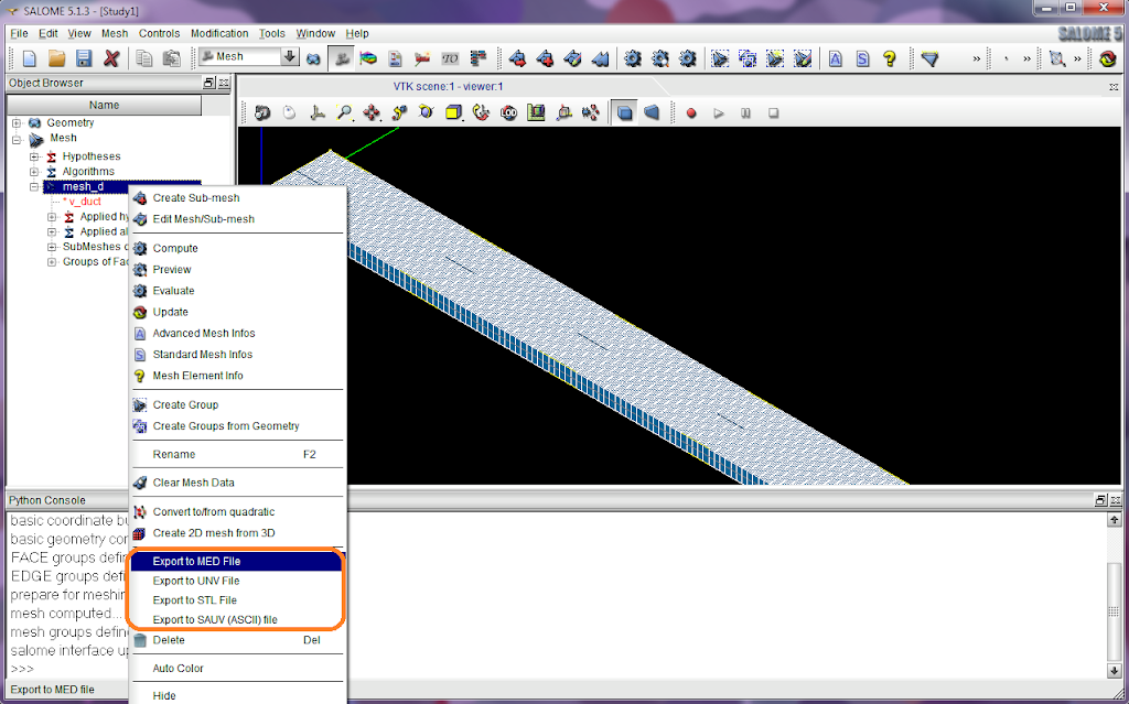
Finally a file 'mesh_d.med' (or 'mesh_d.unv') is obtained. This is the mesh file we will move to Code_Saturne's MESH directory.
CFD solving with Code_Saturne
Please read Part II of this article.
Post-processing with ParaView
Please read Part III of this article.


Hello,
ReplyDeleteI was wondering if you could help me with some examples(geometry, mesh and exporting to med file) of modelling in Salome an airflow from a device(from a 3d room) into the same room. The room has also some objects(boxes) in it. All of this should be done 3D, using python scripts.
Thank you,
Ana
Hi Ana,
ReplyDeleteYes, I could if you can provide more details. I will try to help.
Best regards,
Well, I work on a project which aims to simulate an airflow in a room of servers. The input from the user is the dimension(3D) of the room, dimensions(3D) of several objects in the room(represented by rectangles) and position of an air source, let's say an air conditioning unit.
ReplyDeleteThe user interface is done, and now I have to create in Salome a geometry and a mesh based on user's given dimensions. I'm kind of new with Salome and I have to do this part with scripts in python, the result will be processed later on using Saturne. As an example, let's say the room has the following dimensions: height: 3000 mm, lenght: 9000 mmm, width: 5000 mm and in the middle of the room, on the floor is a rectangle of height: 1000 mm, lenght: 2000 mmm and width: 2000 mm.
In addition to this, I also don't know how to place the air source in the room. I think the position has no relevance now, since it can be changed easily by providing some coordinates.
Here is my e-mail and gtalk address: ana.stroe@gmail.com. I've been reading some tutorials, but none give me a solution on how this can be done.
Thank you again,
Ana
Hi Ana,
ReplyDeleteWell, it doesn't seem to be difficult. I have contacted your email.
Best regards,
hi can you post this example on line. thanks
ReplyDeleteHi agentZ,
ReplyDeleteAbsolutely I can. You need this python code file, or any others? Please leave an email address and I'll send to you.
Best regards,
Thanks agentZ.
ReplyDeleteI'm more interested on code_saturne part. So If you can send me the mesh and xml that would be great. or maybe just the whole study directory (I do not want to mess up with files).
thanks.
email: florante_kho@yahoo.com
Hi agentZ,
ReplyDeleteI have sent the package to you. Please confirm if you receive it.
If there are other problems, don't hesitate to communicate.
Best regards,
Hi,
ReplyDeleteI noticed that some time ago you posted a question on the Salome forum about how to generate a periodic mesh on paired-faces of a cubic box.
Im currently working on implementing OCC techniques into a maxwell equation solver where I am facing exactly the same problem.
To me it seems this should be possible with the SMESH module by functions like smeshDC::Mesh.TranslateMakeMesh, but Im not shure if it could work.
Could you find a solution for this problem?
Thanks a lot for any comments on this,
Mark
My email is mark.blome (at) gmail dot com
Hello Mark,
ReplyDeleteCan you achieve to do that by controlling the mesh profile along each segment of the cubic box? The code in this post can be referred as well.
I didn't use the Mesh.TranslateMakeMesh function. If your scenario is complex when using the method presented here, we can try to use the function instead. Can you email a drawing for me to understand the requirements you really want? My gmail account is salad00.
Best regards,
Hi,
ReplyDeleteThanks for this tutorial. I am trying to generate the mesh for the simple junction tutorial in a Code-Saturne tutorial found in the doc directory of Code-Saturne 2-rc1. I am doing the first section and the mesh seems to be similar to the one you have got here for the channel flow. I tried to implement the methods you have used for generating the mesh but did did not manage to do it.
Do you know of any tutorials or example where they explain mesh generation of this kind and also is what you have used here the same idea as the one used in the saturne tutorial?
Thank you in advance.
Regards,
Hello Mina,
ReplyDeleteThe basic idea of this meshing method is to control the profiles of the mesh density distributions along different directions. I used analytical expressions to define the profiles. Another pre-condition is it is a structured mesh. Please try to say what difficulties you encountered.
I used python code directly in this post because it is the most precise way. I wrote these code by myself without referring to any tutorials or examples rather than the SALOME documents. You can execute them in SALOME - no problem. I also suggest you modify the code to suit your case firstly.
Saturne doesn't include a mesh generation tutorial. You can probably find some examples on the SALOME website.
Good luck :)
Best regards,
Thanks for the advice. I managed to do the mesh in Salome. :)
ReplyDeleteBest Regards,
Hi mina,
ReplyDeleteFantastic to hear that :)
Best regards,
They help minimise your loss which helps you with CFD Tip number 1 – preserve precious capital. Every trade your enter should have a clearly defined CFD stop assigned to it and ideally you should have identified that CFD stop outside of live trading.
ReplyDeleteHi,
ReplyDeleteI am interested in the room cooling python & xml code too. Would you kindly email it to me please? Thank you.
Hi salad, very useful example! Thanks a lot! I am trying to adjust the python-script to a 3d duct, but encounter error messages. I have copied this part:
ReplyDelete# for inlet & outlet, use parabolic mesh density profile
algo1d_let = mesh_d.Segment(g_let)
seg = algo1d_let.NumberOfSegments(50)
seg.SetDistrType(3)
seg.SetConversionMode(1)
seg.SetExpressionFunction('(t-0.5)^2+0.1')
and changed the "let" part to "extru" to have a square duct. Everytime Salpme tells me "mesh_d" has not been computed".
Can you post (or email: joostdeswart at hotmail.com) the part of the script that has to be changed in order to have a 3d (meshed) duct?
Thanks a lot,
joost
setting the extrusion length to unit * 5 does not work. Apparently, making a 3d geometry should be done in a different way. Does anyone have an example of a 3d duct?
ReplyDeleteHello Joost,
ReplyDeleteCan you post your code here and I can try to help?
Best regards,
Hello Pashya, I'm new with Salome. I read your tutotrial1 wrote the batch, saved it with lamflow.py used the pyton-files of Salome clicked Control T and encountered on line 2 "no encoding declared..". I checked with python.org/peps/pep-0263.html but frankly I did not know which type of encoding is appropriate, Would you help me? Thanks a lot! Best regards, Peter
ReplyDelete