When fluid flows along a 2D channel, which is between two infinite parallel plates, with a relatively low velocity (laminar flow), a hydraulic stable status can be achieved after a certain distance (entrance length). This stable flow status is named as
hydraulically fully developed flow. Furthermore, if there is heat flux at the duct surfaces, the fluid near the wall will be warmed up, and a
thermal boundary layer is then formed.
For a flow along a channel without heated, after it is fully developed, the velocity pattern at a cross area is parabolic. However, if the flow is also heated, the parabolic velocity pattern will be twisted because of the viscosity dependency of the fluid (this is true for many types of liquid). This phenomenon is pictorially shown as the figure below, in which (a) is the parabolic velocity profile, and (b) is the distorted profile in a heated duct due to the temperature dependency of the fluid viscosity.

Denote the duct height as
H, duct length as
L, fluid density as

, and the average velocity in the duct region as
U. Then the pressure drop between the two ends of the duct can be expressed as

in which

is defined as friction coefficient. Actually this equation says the active pressure force has to balance the friction force due to shear stress, which is finally related to the fluid viscosity.
Anyway, I select this example to show a simple CFD calculation, because its simple geometry. Using SALOME we can very quickly build up a geometry and then mesh it. Probably an expected structured mesh of the channel can be like this. It is better to have dense mesh near the inlet and the walls of the duct.
 Geometry and mesh using SALOME
According to the philosophy of
executing commands on terminals, I'll use
python scripts to re-perform the procedure of modelling in SALOME.
#######################################################################

# Geometry construction and meshing creation for a typical

#   2d channel flow between two infinite parallel plates.

#

# Written by: salad

#   Manchester, UK

#   06/02/2010

#######################################################################
How to execute these scripts? New a blank study in SALOME and then a 'Python Console' can be seen at the bottom of the window. Input or copy scripts into the console and press Enter to execute them. Scripts can also be saved in a .py file, and with the menu item 'File >> Load Script...' a dialog 'Load python script' can help load script files and execute them as a batch. 'Ctrl+T' is the shortcut to call the dialog.
Ok, let's start.
1. Import the necessary libraries and define the related dimensions. We are going to build a duct with height 5 mm and length 100 mm.
import os

import sys

import salome

from math import *

from geompy import *

import copy


# basic unit

unit = 0.001

# extrusion length

extru = unit


duct_height = unit * 5

duct_length = unit * 100
'extru' is the extrusion length along the z axis. This length will be meshed with only one cell. Actually Code_Saturne only handles 3D meshes with FVM. Therefore, to simulate a 2D mesh, it is a good practice to extrude the 2D mesh with a 1 cell layer thickness.
2. Build the basic coordinate.
#

# basic coordinate

#

p0 = MakeVertex(0, 0, 0)

dx = MakeVectorDXDYDZ(unit, 0, 0)

dy = MakeVectorDXDYDZ(0, unit, 0)

dz = MakeVectorDXDYDZ(0, 0, unit)

addToStudy(p0, "p0")

addToStudy(dx, "dx")

addToStudy(dy, "dy")

addToStudy(dz, "dz")


print "basic coordinate built..."
3. Construct the channel geometry. The geometry modelling procedure can be briefly expressed as: points => edges => faces => extrusion. Points are constructed with coordinates, edges are defined by linking points, and faces are then defined by specifying its edges. Finally extrusion helps convert the 2D geometry to 3D.
#

# geometry construction

#


# points

p1 = MakeVertex(duct_length, 0, 0)

p2 = MakeVertex(0, duct_height, 0)

p3 = MakeVertex(duct_length, duct_height, 0)


# build edges

e0 = MakeEdge(p0, p1)

e1 = MakeEdge(p2, p3)

e2 = MakeEdge(p0, p2)

e3 = MakeEdge(p1, p3)


# build face

f_duct = MakeFaceWires([e0, e1, e2, e3], 1)


# extrude along the z axis

v_duct = MakePrismVecH(f_duct, dz, extru)

addToStudy(v_duct, "v_duct")


print "channel geometry constructed..."
4. Define the groups. Groups are necessary because they correspond to the boundaries used during CFD calculations. Here we define the geometry groups and these groups will then be encapsulated into mesh groups later. Mesh groups will be used to define boundary conditions when using Code_Saturne.
Firstly, define the face groups. Functions used in the python script can be looked up in the SALOME document.
# FACE groups definition:

# 1. inlet

# 2. outlet

# 3. bottom

# 4. top

# 5. sym


# sym is declared and filled

sub_faces = SubShapeAllSorted(v_duct, ShapeType["FACE"])

g_sym = CreateGroup(v_duct, ShapeType["FACE"])

UnionList(g_sym, sub_faces)


# inlet

sub_faces = GetShapesOnPlane(v_duct, ShapeType["FACE"], dx, GEOM.ST_ON)


g_inlet = CreateGroup(v_duct, ShapeType["FACE"])

UnionList(g_inlet, sub_faces)

DifferenceList(g_sym, sub_faces)


addToStudyInFather(v_duct, g_inlet, "inlet")


# outlet

sub_faces = GetShapesOnPlaneWithLocation(v_duct, ShapeType["FACE"], dx, p1, GEOM.ST_ON)


g_outlet = CreateGroup(v_duct, ShapeType["FACE"])

UnionList(g_outlet, sub_faces)

DifferenceList(g_sym, sub_faces)


addToStudyInFather(v_duct, g_outlet, "outlet")


# bottom

sub_faces = GetShapesOnPlane(v_duct, ShapeType["FACE"], dy, GEOM.ST_ON)


g_bottom = CreateGroup(v_duct, ShapeType["FACE"])

UnionList(g_bottom, sub_faces)

DifferenceList(g_sym, sub_faces)


addToStudyInFather(v_duct, g_bottom, "bottom")


# top

sub_faces = GetShapesOnPlaneWithLocation(v_duct, ShapeType["FACE"], dy, p2, GEOM.ST_ON)


g_top = CreateGroup(v_duct, ShapeType["FACE"])

UnionList(g_top, sub_faces)

DifferenceList(g_sym, sub_faces)


addToStudyInFather(v_duct, g_top, "top")


# sym is finally obtained

addToStudyInFather(v_duct, g_sym, "sym")


print "FACE groups defined..."
Then define the edge groups.
# EDGE groups definition:

# 1. let (inlet & outlet of the channel)

# 2. tb (top & bottom of the channel)

# 3. extru (the extrusion length)


# let

g_let = GetEdgesByLength(v_duct, duct_height, duct_height, 1, 1)

addToStudyInFather(v_duct, g_let, "let")


# tb

g_tb = GetEdgesByLength(v_duct, duct_length, duct_length, 1, 1)

addToStudyInFather(v_duct, g_tb, "tb")


# extru

g_extru = GetEdgesByLength(v_duct, extru, extru, 1, 1)

addToStudyInFather(v_duct, g_extru, "extru")


print "EDGE groups defined..."
5. Mesh. Till now the geometry is already produced. Meshing can be performed with the script below. Note that the expressions, which define the corresponding mesh density profiles, can be edited to any others if necessary.
#

# meshing

#

import smesh

import StdMeshers


mesh_d = smesh.Mesh(v_duct, "mesh_d")


print "prepare for meshing..."


# construction of mesh


# as default, a 1D edge is meshed with only 1 cell

# it is for the extrusion length

algo1d = mesh_d.Segment()

algo1d.NumberOfSegments(1)


# structured rectangular mesh is preferred for 2D faces

algo2d = mesh_d.Quadrangle()

algo2d.QuadranglePreference()


algo3d = mesh_d.Hexahedron()


# submesh


# for inlet & outlet, use parabolic mesh density profile

algo1d_let = mesh_d.Segment(g_let)

seg = algo1d_let.NumberOfSegments(50)

seg.SetDistrType(3)

seg.SetConversionMode(1)

seg.SetExpressionFunction('(t-0.5)^2+0.1')


# for top & bottom, use a decreasing profile from the inlet to the outlet

algo1d_tb = mesh_d.Segment(g_tb)

seg = algo1d_tb.NumberOfSegments(250)

seg.SetDistrType(3)

seg.SetConversionMode(0)

seg.SetExpressionFunction('(t-1)^4+0.1')


status = mesh_d.Compute()


print "mesh computed..."
The same with the geometry modelling, groups of mesh are also defined accordingly.
#

# mesh groups

#


mesh_d.GroupOnGeom(g_inlet, "inlet")

mesh_d.GroupOnGeom(g_outlet, "outlet")

mesh_d.GroupOnGeom(g_bottom, "bottom")

mesh_d.GroupOnGeom(g_top, "top")

mesh_d.GroupOnGeom(g_sym, "sym")


print "mesh groups defined..."
Arriving at this, you should be able to update the SALOME GUI to see the mesh generated, and also judge whether it is what you want.
# update

salome.sg.updateObjBrowser(1)
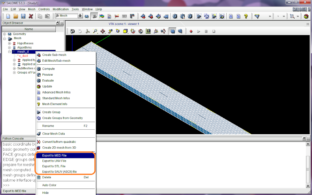
6. Output. After the mesh is produced, it has to be saved into a file before using it with Code_Saturne. In SALOME, right-click the object 'mesh_d' and from the context menu we can see that SALOME supports exporting to MED and UNV file formats. If your Code_Saturne was compiled with MED support, I recommend to use MED because of its smaller file size; or UNV can be used.
Finally a file 'mesh_d.med' (or 'mesh_d.unv') is obtained. This is the mesh file we will move to Code_Saturne's
MESH directory.
CFD solving with Code_Saturne
Please read
Part II of this article.
Post-processing with ParaView
Please read
Part III of this article.


